Tutorial: narrowTmember
Prepared by Philip Cardiff
Tutorial Aims
- Demonstrate how to perform a linear-static stress analysis of a 3-D engineering component in solids4foam;
- Compares the performance of two finite volume solid models: (i) the coupled cell-centred
coupledUnsLinearGeometryLinearElasticmodel, and (ii) the segregated cell-centredlinearGeometryTotalDisplacementmodel. - Shows how to modify a case, which uses the
coupledUnsLinearGeometryLinearElasticsolid model, to use thelinearGeometryTotalDisplacementsolid model.
Case Overview
This case comprises a narrow engineering component with a T cross-section (Figure 1). This case was proposed as a benchmark by Demirdzic et al., 1997, Benchmark solutions of some structural analysis problems using the finite-volume method and multigrid acceleration. Int J Numer Methods Eng. Due to symmetry, the solution domain consists of one-quarter of the component. A constant negative pressure of 1 MPa is applied to the lower surface, and the upper left surface is fully clamped (Figure 1). The Young's modulus is 210 GPa, and Poisson's ratio is 0.3. A radius \(R = 5\) mm hole is located at the expected stress concentration. Four separate systematically refined hexahedral meshes (624, 4992, 39 936, and 319 488 cells) are examined here, mimicking the meshes employed by Demirdzic et al.; the coarsest mesh is shown in Figure 2.
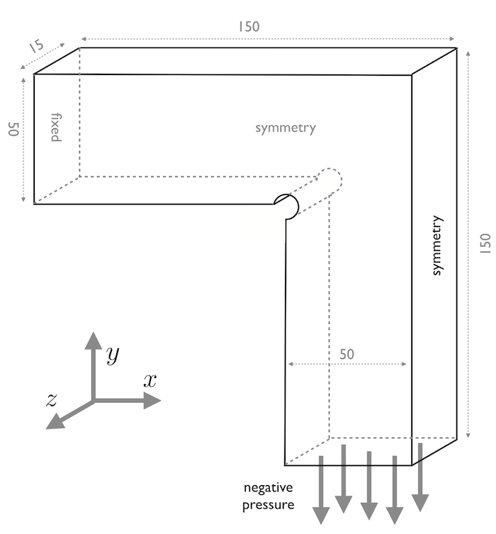
Figure 1: Geometry and loading with dimensions in mm.
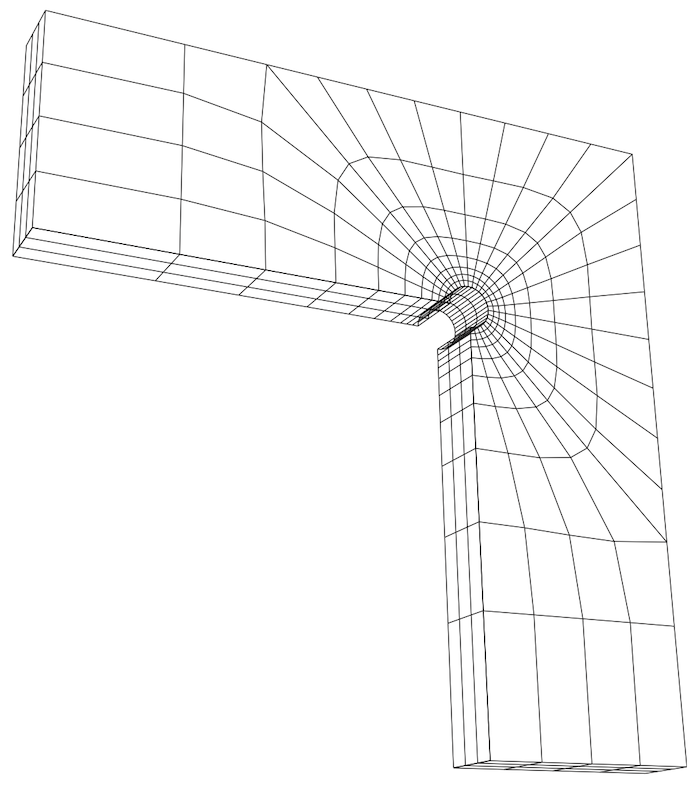
Figure 2: Coarest hexahedral mesh (624 cells)
Running the Case
The tutorial case is located at solids4foam/tutorials/solids/linearElasticity/narrowTmember. The case can be run using the included Allrun script, i.e. ./Allrun. In this case, the Allrun simply consists of creating the mesh using blockMesh (./blockMesh) followed by running the solids4foam solver (./solids4Foam).
The coupled version of this case, which uses the coupledUnsLinearGeometryLinearElastic, can currently only be run using solids4foam built on foam-extend.
To modify the case to run with the segregated linearGeometryTotalDisplacement solid model, the following changes are required:
- In
0/D- Replace
blockSolidTractionwithsolidTraction - Replace
blockFixedDisplacementwithfixedDisplacement - Replace
blockFixedDisplacementZeroShearwithfixedDisplacementZeroShear
- Replace
- In
constant/solidProperties- Replace
solidModel coupledUnsLinearGeometryLinearElastic;withsolidModel linearGeometryTotalDisplacement; - (This is already present in the tutorial case) Add the following dictionary
linearGeometryTotalDisplacementCoeffs {}
- Replace
- In
system/fvSchemes- Set the default
gradSchemestopointCellsLeastSquaresfor OpenFOAM.com/OpenFOAM.org, orleastSquaresfor foam-extend - Set the default
divSchemestoGauss linear - Set the default
laplacianSchemestoGauss linear skewCorrected 1 - Set the default
interpolationSchemestolinear
- Set the default
The case can the be run as before, i.e. > blockMesh && solids4Foam.
Expected Results
Figure 3 shows the \(\sigma_{xx}\) and \(\sigma_yy\) stress distributions on the plane z = 0 m (symmetry plane) for the finest mesh. The predictions agree closely with the results of Demirdzic et al. Further comparisons can be found in Cardiff et al., 2016, A block-coupled Finite Volume methodology for linear elasticity and unstructured meshes, Comp. and Struct.
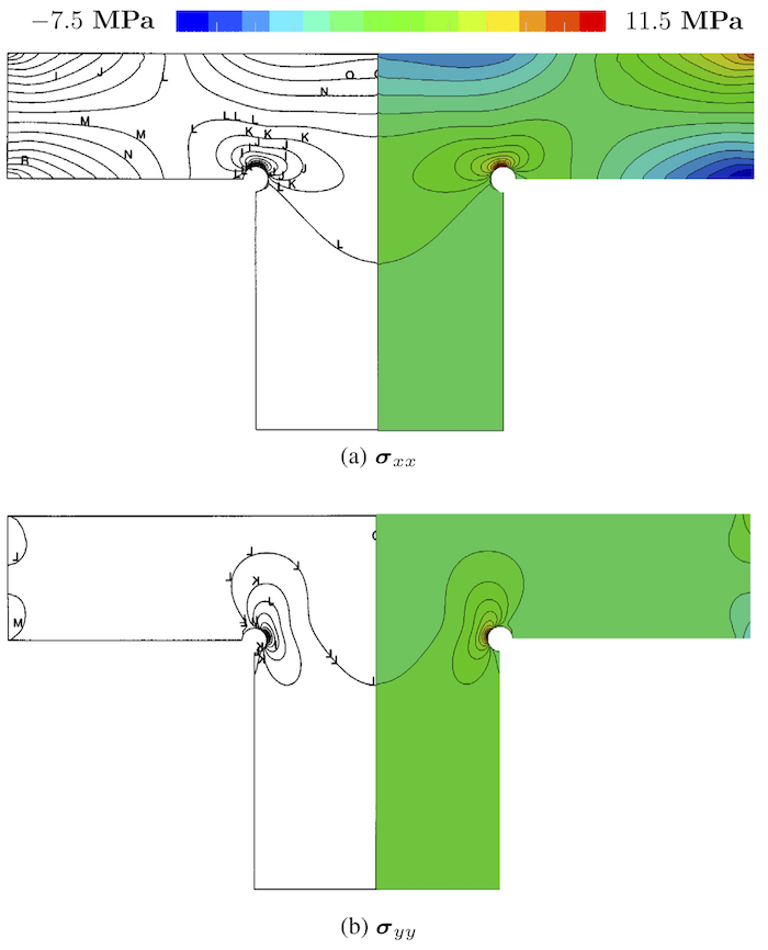
Figure 3: Predicted stress component distributions on the plane z = 0:0 m (right) compared with results from Demirdzic et al. (left).
The wall-clock times and memory requirements for each run are given in Table 1, where the results for the coupled and segregated solid models are compared. The coupled solver used a bi-conjugate gradient stabilised linear solver with ILU(0) preconditioner, while the segregated solver used a conjugate gradient linear solver with ILU(0) preconditioner. Both approaches used a solution tolerance of \(1 \times 10^{-6}\). In this case, the coupled solver is approximately four times faster than the segregated solver but requires about four times more memory.
The wall-clock times given in Table 1 were recorded in 2015 using one core of a 2.4 GHz Intel Ivy Bridge CPU. Better performance can be expected using a new machine.
Table 1: Wall-clock time (in s) and maximum memory usage (in MB).
| Mesh | Coupled | Segregated | ||
|---|---|---|---|---|
| Time | Memory | Time | Memory | |
| 624 | 0.2 | 15 | 0.7 | 8 |
| 4 992 | 2 | 58 | 6 | 24 |
| 39 936 | 29 | 340 | 98 | 88 |
| 319 488 | 421 | 2 400 | 2 220 | 560 |
The coupledUnsLinearGeometryLinearElastic solid model currently does not run in parallel. For a coupled solid model that does run in parallel, use the vertexCentredLinGeomSolid solid model.