Square plate with transverse pressure: squarePlate
Prepared by Philip Cardiff and Ivan Batistić
Tutorial Aims
- Demonstrate analysing a simple plate-bending problem using a finite area implementation of a Kirchoff-Love plate model.
This case currently only runs with foam extend as it uses the foam extend finite area discretisation framework.
Plate Theory Assumptions
Two types of beam/plate/shell theory are widely used:
- Euler–Bernoulli beam theory, corresponding to Kirchhoff–Love shell theory
- The planes normal to the midline are assumed to remain plane and normal (no shear stress); this is also called engineering beam theory.
- Timoshenko beam theory, corresponding to Mindlin–Reissner shell theory
- The planes normal to the midline are assumed to remain plane but not necessarily normal (shear stress may be non-zero); this is also called shear beam theory.
Kirchhoff–Love shell theory is a subset of Mindlin–Reissner shell theory, i.e. Mindlin–Reissner is applicable in every case that Kirchhoff–Love shell theory is applicable, but Kirchhoff–Love theory is not applicable in every case that Mindlin–Reissner theory is applicable. The following table demonstrates the valid length \(L\) to thickness \(h\) ranges for Kirchhoff and Mindlin approaches relative to a 3-D continuum approach.
| Kirchhoff | Mindlin | 3-D continuum | |
|---|---|---|---|
| Thin: \(L/h > 10\) | ✓ | ✓ | ✓ |
| Moderately thick: \(L/h > 5\) | x | ✓ | ✓ |
| Thick: \(L/h < 5\) | x | x | ✓ |
Kirchhoff-Love Plate Formulation
For thin plates \((L/h > 10)\), Kirchhoff–Love shell theory allows the conservation of momentum to be reformulated into a fourth-order partial differential equation known as the biharmonic equation, where the unknown scalar, \(w\), is the transverse displacement (displacement normal to the plate): \(\rho h \frac{\partial^2 w}{\partial t^2} = -D \nabla^2 \nabla^2 w + p,\) The plate density is \(\rho\) , \(h\) is its thickness, \(D\) is its bending stiffness (a function of the Young's modulus \(E\), Poisson's ration \(\nu\) and \(h\)), and \(p\) is the applied external pressure (transverse direction). This fourth-order equation can be re-written as two coupled second-order equations: \(\rho h \frac{\partial^2 w}{\partial t^2} = \nabla^2 M + p, \qquad \text{where M is:}\qquad M = - D \nabla^2 w.\) These coupled second order equations are the starting point for finite area discretisation employed here, where the finite area method is a form of finite volume method applied to surfaces in 3-D space.
Case Overview
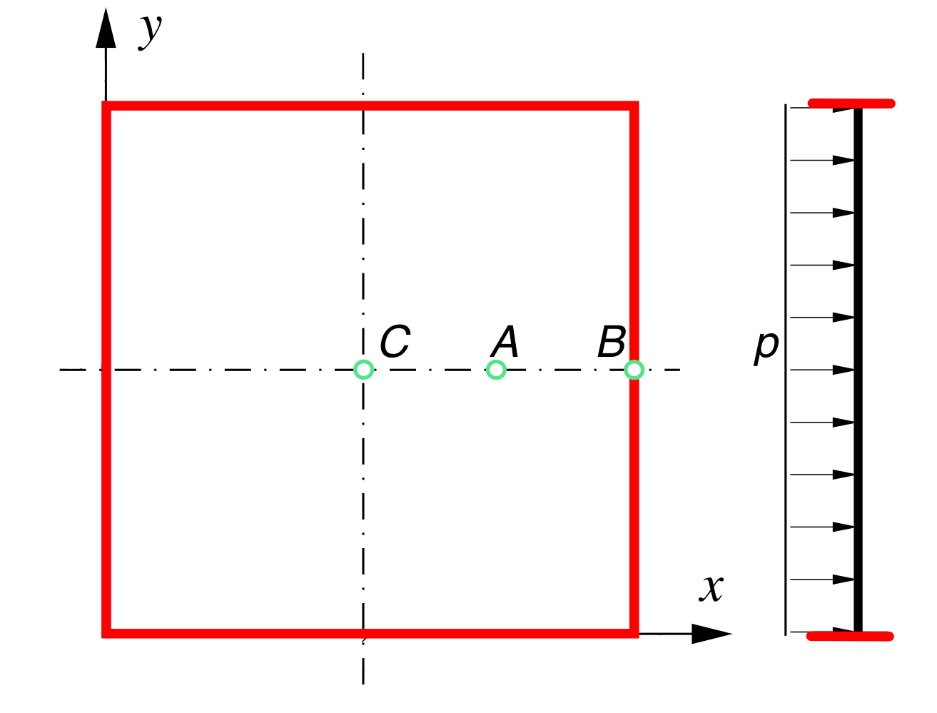
The dimensions of the plate are \(L \times L \times h = 10\) m \(\times~10\) m \(\times~0.1\) m (the length-to-thickness ratio is \(L/h = 10\)). The plate is loaded by a uniform external pressure \(p = 1000\) Pa (Figure 1). The plate weight is ignored. The Young's modulus \(E\) and the Poisson's ratio \(\nu\) of the material are \(200\) GPa and \(0.3\), respectively. The use of symmetry boundaries allows the reduction of the computational domain to a quarter of the plate. However, the symmetry planes are not used here so that the symmetric distribution of solution variables can be verified. Regarding the edges of the plates (colored red in Figure 1), two configurations are considered:
- The plate is clamped at all sides (zero displacement and zero rotation);
- All edges are simply supported (zero displacement and zero moment/torque).
Expected Results
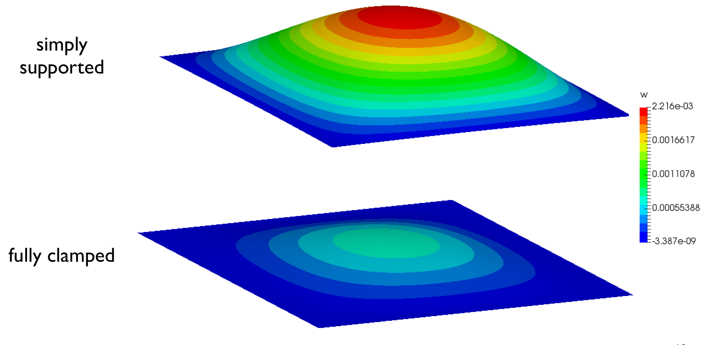
The deflection in the simply supported case is expected to be larger as the plate can more freely bend, as shown in Figure 2.
By uncommenting the relevant lines in 0/M, one can switch between simply supported and fully clamped boundary conditions.
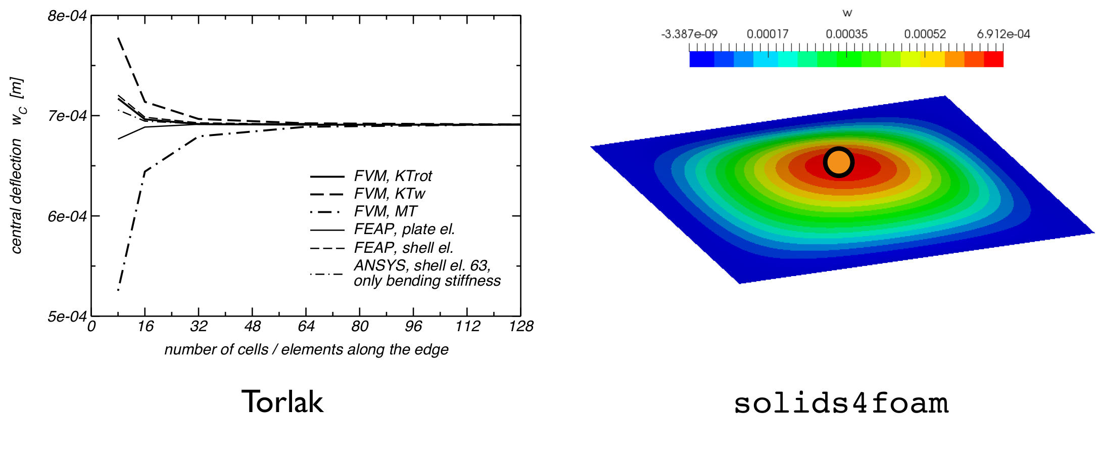
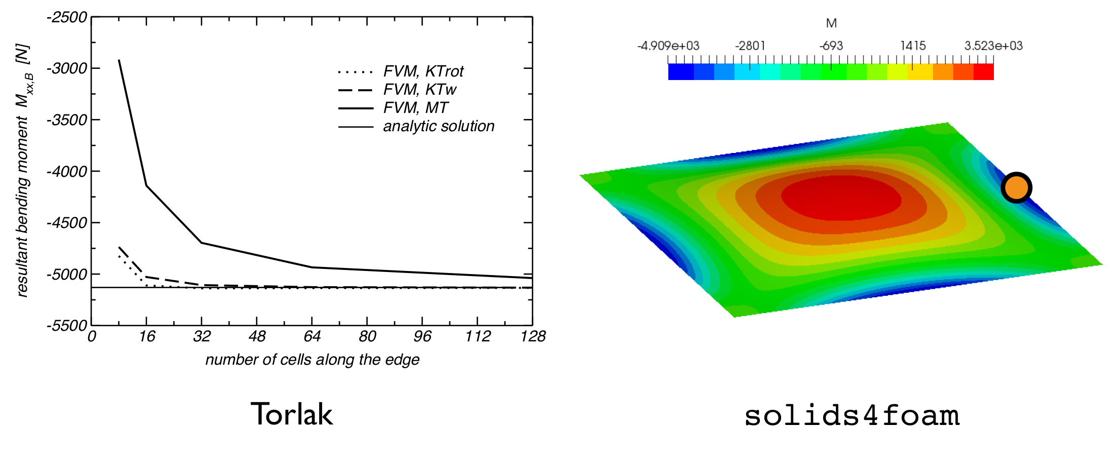
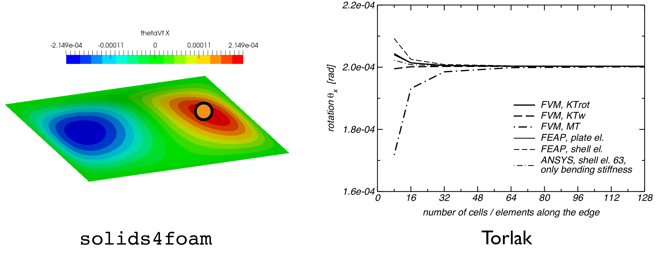
The results for the fully clamped case can be compared with values from literature [1]. Figures 3, 4, and 5 compare the predicted deflections, bending moment, and rotations. The solids4foam predictions closley match the reference results [1].
Running the Case
The tutorial case is located at solids4foam/tutorials/solids/beamsPlatesShells/squarePlate. The case can be run using the included Allrun script, i.e. > ./Allrun. In this case, the Allrun consists of creating the mesh using blockMesh (> blockMesh) after which makeFaMesh (> makeFaMesh) command is used to create finite area mesh. Finally, the solids4foam solver is used to run the case (> solids4Foam).
References
[1] M. Torlak, A Finite-Volume Method for Coupled Numerical Analysis of Incompressible Fluid Flow and Linear Deformation of Elastic Structures. PhD thesis, Technischen Universität Hamburg-Harburg, 2006.