Tutorial: cylinderCrush
Prepared by Iago Lessa de Oliveira
Tutorial Aims
- Exemplify the use of a hyperelastic mechanical law with large deformations and a solid contact boundary condition.
- Compare the convergence behaviour of updated and total Lagrangian formulations.
This tutorial currently only works with foam-extend-4.1.
Case Overview
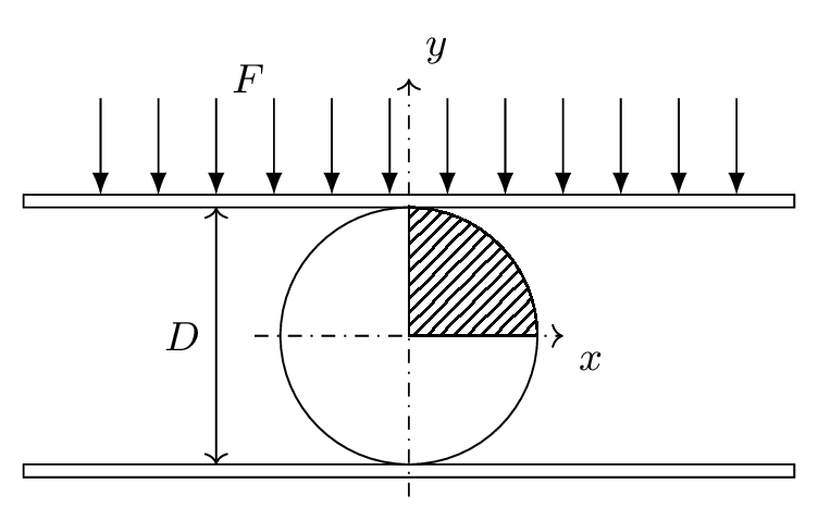
Figure 1: Solid cylinder compressed between two rigid plates
The third benchmark is a solid cylinder made of a rubbery material crushed between two rigid plates, as schematically shown in Figure 1. The cylinder has a diameter of 0.4 m and is compressed between rigid plates with a total compressed displacement of half its diameter. The contact between the cylinder and plate surfaces was modelled as frictionless (see the solidContact boundary condition setup in the 0/DD file).
This problem was investigated by [1] T. Sussman and K.-J. Bathe, "A finite element formulation for nonlinear incompresible elastic and inelastic analysis," Computers and Structures, vol. 26, pp. 357–409, 1987., who assumed a nearly-incompressible behaviour of the material, and also by I. Bijelonja, I. Demirdžić, and S. Muzaferija, "A finite volume method for large strain analysis of incompressible hyperelastic materials," International Journal for Numerical Methods in Engineering, vol. 64, pp. 1594–1609, Nov. 2005, who modelled the cylinder material as purely incompressible. In this tutorial, the same material law employed by both studies was used: the Mooney-Rivlin law with c10 = 0.293 MPa, c01 = 0.177 MPa, and the bulk modulus 1410 MPa. Note that this material is much less stiff than the material assumed in the previous two tutorials.
The domain used was only a quarter of the cylinder due to symmetry (hatched area in Figure 1). A mesh with 500 quadrilateral control volumes arranged in a block-structured mesh was simulated, and the updated Lagrangian approach was employed for the results shown below, indicated by the solidModel nonLinearGeometryUpdatedLagrangian. The plate is linearly displaced in 30 increments.
Expected Results
Figure 2 shows the displacement of the mesh of the (a) undeformed configuration and an intermediate and final instant of the simulation (b and c, respectively). Figure 3 shows the Von Mises stress field for the intermediate and final configuration of the cylinder, where we can see that the maximum stress occurs at the cylinder centre.
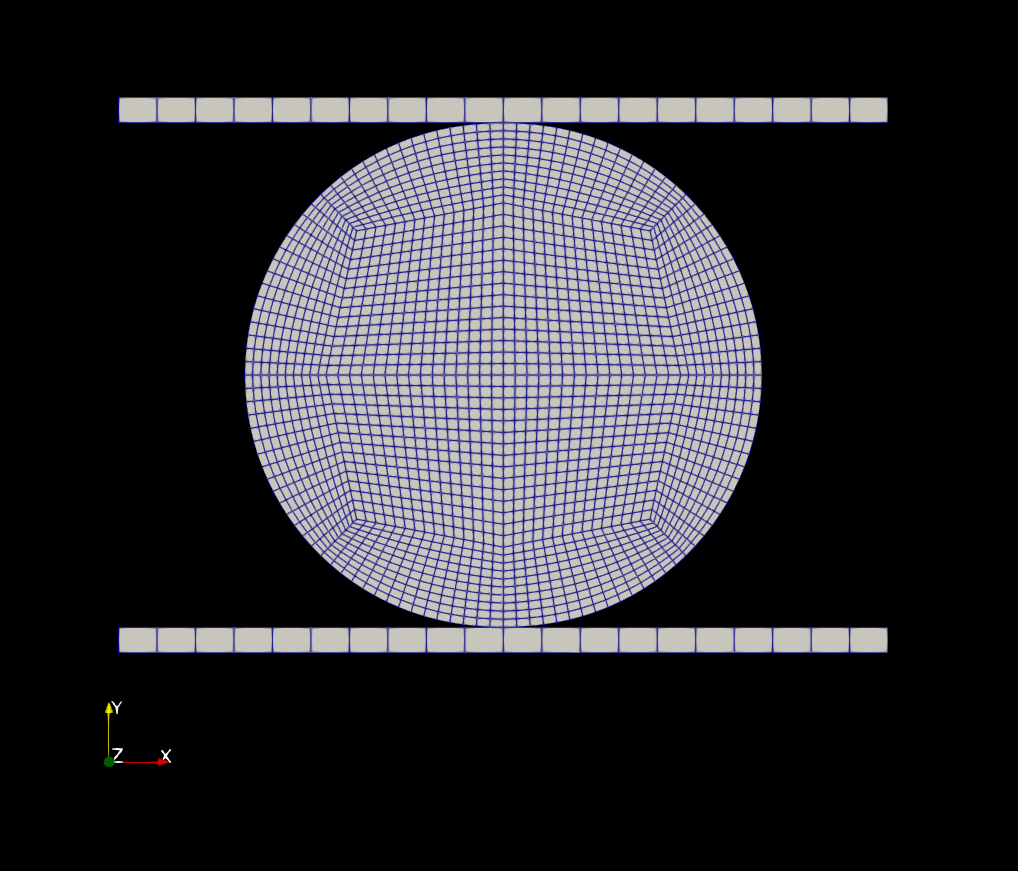
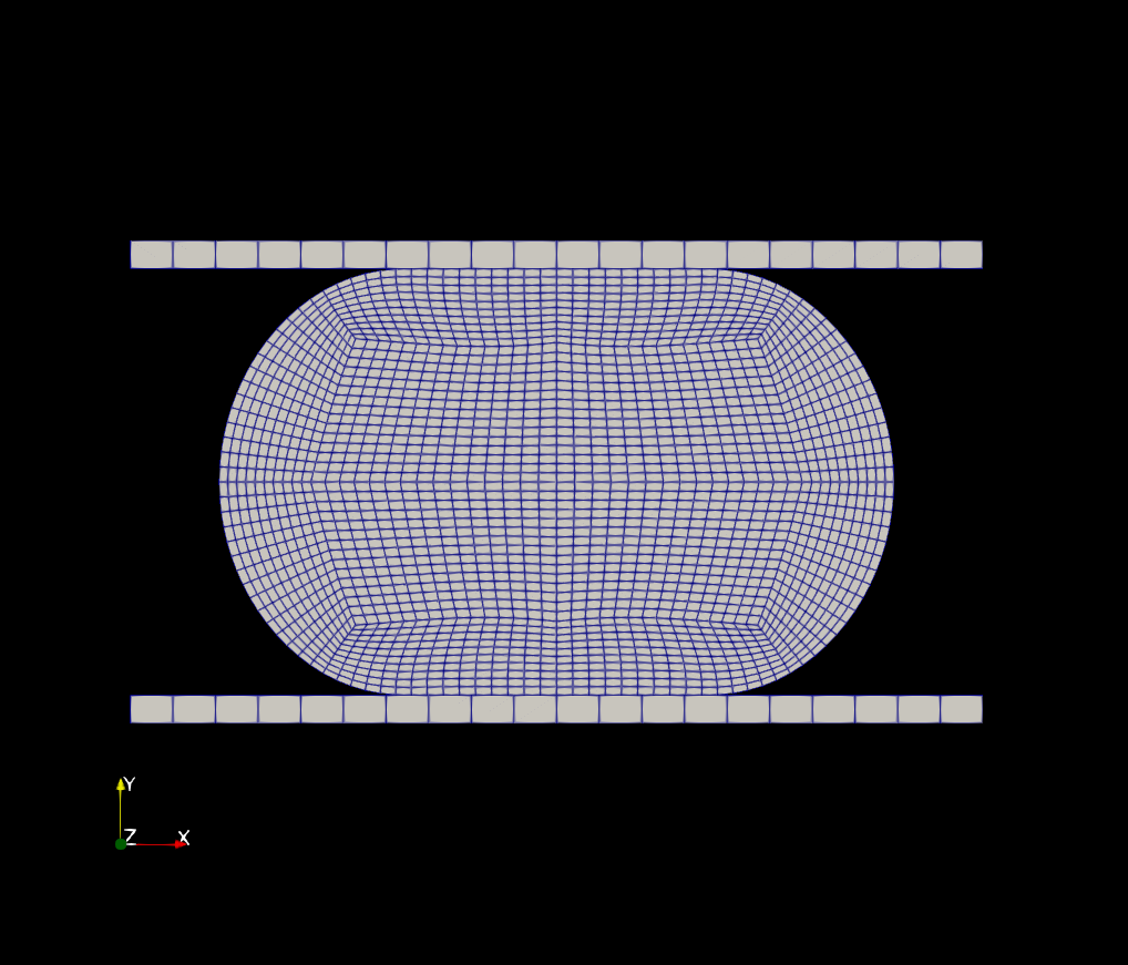
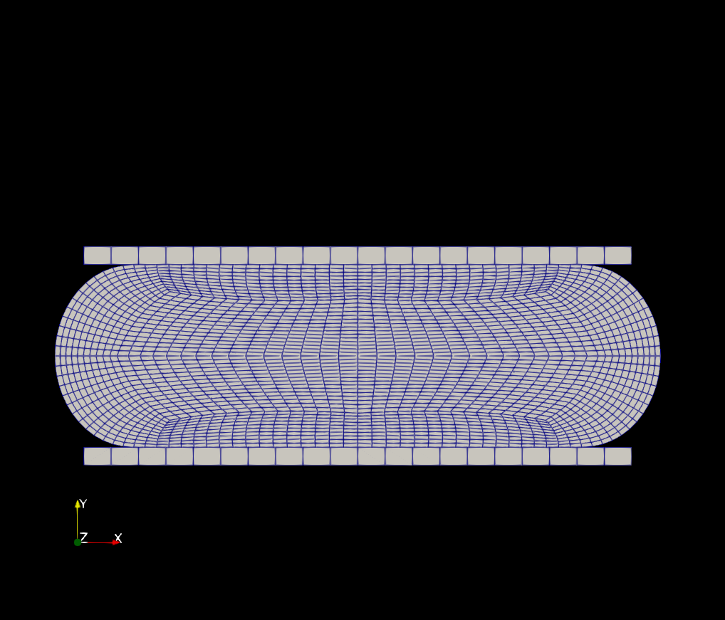
Figure 2: Mesh of the undeformed configuration and the deformed mesh at an intermediate and final instant.
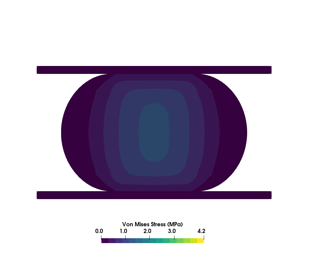
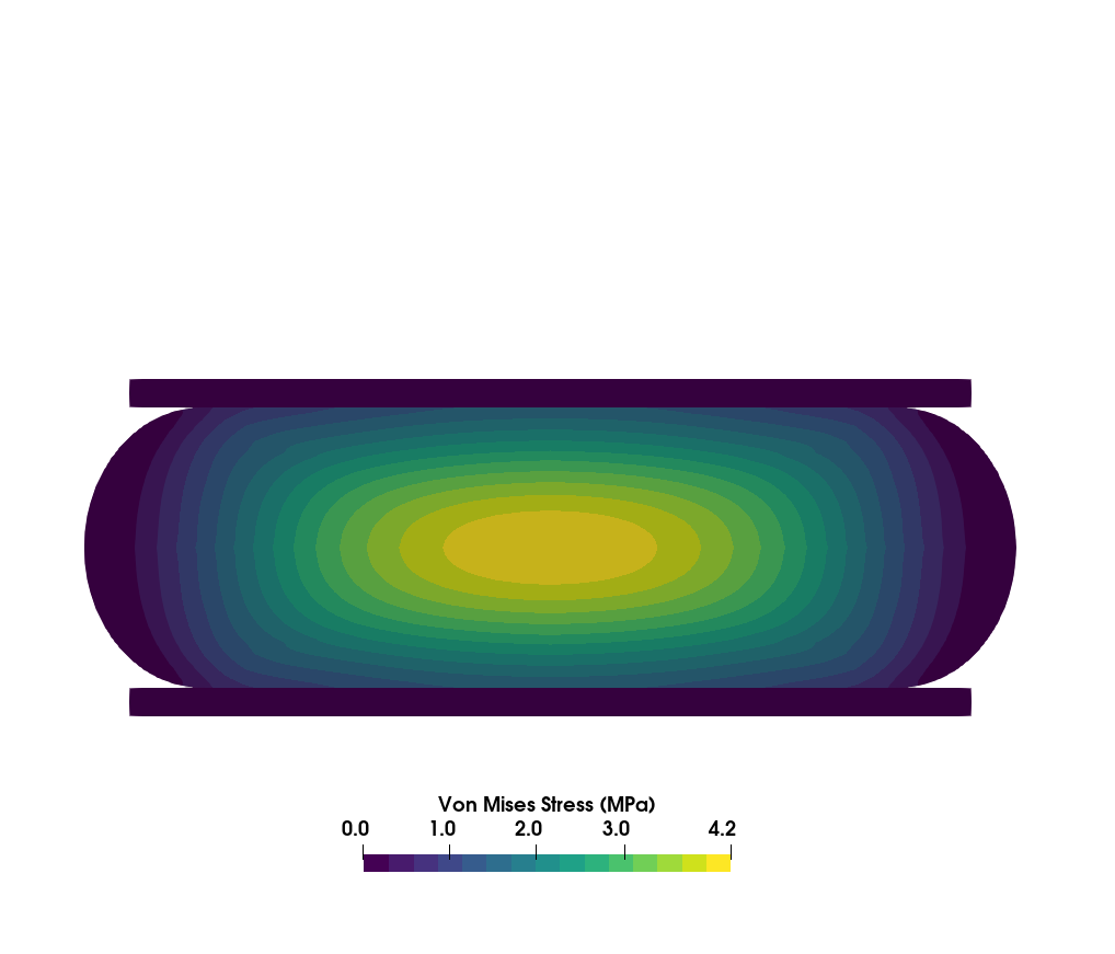
Figure 3: Von Mises stress fields at the intermediate and final instants of time.
The verification of the solution given by solids4Foam can be seen in Figure 4, which shows the displacement force applied to the cylinder as a function of the plate's vertical displacement. The plot compares the numerical solution using the finite element method (FEM) solution provided by Bijelonja et al. (2005).
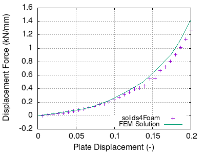
Figure 4: Displacement force versus deflection of the cylinder with solid4Foam and a reference solution using the FEM method published in Bijelonja et al. (2005).
Note from Figures 2 and 3 that the deformation of this case is quite large, with the mesh being considerably deformed towards the later time steps. It is instructive in this tutorial to assess the impact of the updated and total Lagrangian formulations on the convergence of the case. To that end, we first ran this tutorial with the nonLinearGeometryUpdatedLagrangian (labelled UL) and, then, nonLinearGeometryTotalLagrangianTotalDisplacement (labelled TLTD) andnonLinearGeometryTotalLagrangian (labelled TL) that uses the total Lagrangian formulation but with the total and incremental displacements, respectively. The comparison is shown in Figure 5 with the residuals of the second and last time steps.
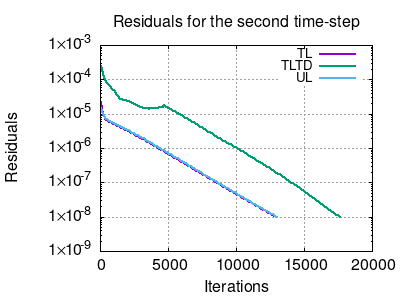

Figure 5: Residuals of this tutorial using updated and total Lagrangian approaches at the second (left panel) and last (right panel) time-steps.
Note that there is a change in the best approach according to the instant in time, although the total simulation time was approximately the same. This may also occur depending on the problem you are simulating, so it might be important to perform different tests on the problem you are handling to find the optimal solidModel.
Data Availability
The results and gnuplot scripts used to generate the figures above are available in the solids4foam tutorials benchmark data repository.